We've launched our new site at www.openlighting.org. This wiki will remain and be updated with more technical information.
Difference between revisions of "OLA LED Pixels"
From wiki.openlighting.org
m |
m (→Hardware Setup) |
||
| Line 54: | Line 54: | ||
The simplest setup is to connect SCLK (pin 23) to the pixel string's clock line and MOSI (pin 19) to the pixel string's DATA line. You'll need a separate power supply for the pixel string, check the pixel specifications but 1A per m is a good rule of thumb. Don't forget to connect the ground on the power supply to a ground pin (e.g. 25) on the Pi.Do not connect the 5V rail of the pixel power supply to the Pi. | The simplest setup is to connect SCLK (pin 23) to the pixel string's clock line and MOSI (pin 19) to the pixel string's DATA line. You'll need a separate power supply for the pixel string, check the pixel specifications but 1A per m is a good rule of thumb. Don't forget to connect the ground on the power supply to a ground pin (e.g. 25) on the Pi.Do not connect the 5V rail of the pixel power supply to the Pi. | ||
| + | |||
| + | This may be enough for testing, but | ||
=== Multiplexer === | === Multiplexer === | ||
| Line 61: | Line 63: | ||
TODO: post schematic here | TODO: post schematic here | ||
| − | |||
| − | |||
== OLA SPI Plugin == | == OLA SPI Plugin == | ||
Revision as of 08:34, 14 September 2013
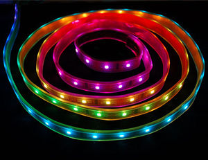
Since March 2013, OLA contains an SPI plugin, which allows you to drive strings of LEDs pixels provided your platform has an SPI interface. Using embedded Linux platforms like the Raspberry Pi, this allows one to build Pixel strings controllable via any of the supported protocols (ArtNet, E1.31, OSC & more) for less than $100.
Alternatively if you don't want network control, you can send DMX512 to the LEDs using the Python, C++ or Java client library running on the host itself.
This page is focused on the Raspberry Pi, but may be applicable to other hardware such as the BeagleBone. If you're using a Raspberry Pi you can save yourself a lot of time by using the pre-built images, see OLA on the Raspberry Pi for details.
Contents
Host Hardware
The Raspberry Pi contains three SPI interfaces, but only one of these is wired to the 26-pin connector. The interface comes with 3 chip-enable (CE) lines but again only two are connected (pins 24 & 26). With the default mode, pin 24 is pulled low when the /dev/spi0.0 device is used and pin 26 is pulled low when /dev/spi0.1 is used.
Here are some timings taken from the Pi:
| SPI Speed | Number of bytes | time taken for write() | Time on the wire |
|---|---|---|---|
| 1MHz | 75 | 13.5ms | 11.1ms |
| 2MHz | 75 | 8.1ms | 5.6ms |
| 4MHz | 75 | 4.7 ms | 3.0 ms |
| 8MHz | 75 | 3.7ms | 1.4ms |
| 12MHz | 75 | 3.2ms | 0.75 ms |
| 1MHz | 516 | 78.5 ms | 76.15 ms |
| 2MHz | 516 | 40.2 ms | 38.2ms |
| 4MHz | 516 | 21.5 ms | 19.1 ms |
| 8MHz | 516 | 12.2ms | 9.6ms |
| 12MHz | 516 | 7.4ms | 4.83 ms |
It also takes somewhere between 3.6 and 4.6 ms to toggle a GPIO pin using the /sys/class/gpio interface. The importance of these numbers will be clear in a minute.
Beyond the Pi, any SPI hardware supported by the Linux kernel should work modulo the timing numbers. By default OLA looks for devices that match the /dev/spi* .
Pixel Hardware
On the pixel side the following is supported:
- LPD8806, e.g. https://www.adafruit.com/products/306. since 0.8.27
- WS2801, e.g. https://www.adafruit.com/products/738, since 0.8.28
Each of these uses 3 DMX slots per pixel, so you can drive up to 170 pixels from a universe of DMX data.
Hardware Setup
The simplest setup is to connect SCLK (pin 23) to the pixel string's clock line and MOSI (pin 19) to the pixel string's DATA line. You'll need a separate power supply for the pixel string, check the pixel specifications but 1A per m is a good rule of thumb. Don't forget to connect the ground on the power supply to a ground pin (e.g. 25) on the Pi.Do not connect the 5V rail of the pixel power supply to the Pi.
This may be enough for testing, but
Multiplexer
If you want to drive more than one string in parallel you'll need to use a de-multiplexer. For a two-line multiplexer one can use the CE0 and CE1 lines to select the output string. To run more than 2 strings you'll need to use some of the GPIO pins as chip-enables.
TODO: post schematic here
OLA SPI Plugin
The OLA SPI plugin is pretty flexible, the primary limitation is how long it takes to write the data out the SPI interface, since this limits the overall refresh rate. Each SPI interface (/dev/spi*) is represented as an OLA Device. Devices can have multiple 'ports' since each port can consume at most one universe of DMX512 data (170 pixels). Each port can be configured (via RDM) with a start address and personality (pixel type). his allows a combination of various strings lengths & pixel hardware types.
Each SPI device uses a backend to write the SPI data. Right now there are two types backends available: a software backend which merges the SPI data from one or more ports, and a hardware backend which uses GPIO to control a hardware demultiplexer.
Timing
It all comes down to timing.
Software Setup
You'll want to see here for suitable udev config, so OLA has permission to talk to your SPI port, as well as some Raspberry Pi specific config.
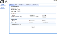
Once you have OLA running it's a matter of patching an SPI Output port to a universe and then patching the desired input port. This can be done from the OLA web UI, which runs on port 9090.
Configuration
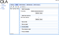
The type of LED drivers, operating mode and DMX Start Address are configurable via RDM. Click on the RDM tab and you'll see the options.
The number of LEDs and SPI speed is set using the ola-spi.conf file.
base_uid = 7a70:00000100
device_prefix = spidev
enabled = true
spidev0.0-dmx-address = 1
spidev0.0-personality = 1
spidev0.0-pixel-count = 25
spidev0.0-spi-speed = 100000
spidev0.1-dmx-address = 1
spidev0.1-personality = 2
spidev0.1-pixel-count = 25
spidev0.1-spi-speed = 100000
Sample Configs
Single Pixel String
Two Pixel Strings, using the CE lines
Related Links
http://www.solderlab.de/index.php/software/glediator (Pixel Control Software that outputs ArtNet)


